Case-Study Case-Study, Neutron Detector, Large Experiment, ESS
Small angle neutron scattering (SANS) is a technique that is applied across a spectrum of scientific disciplines, with users from chemistry, physics, biology, materials science, engineering and geoscience. LoKI is designed primarily with the needs of the soft matter, biophysics and materials science communities in mind and the trend in all of these fields is towards complexity and heterogeneity.

What is a SANS instrument?
A SANS (Small-Angle Neutron Scattering) instrument is a specialized scientific instrument used to study the structure and behavior of materials at the nanoscale level using neutron scattering techniques. Neutron scattering is a powerful tool for investigating the arrangement and interactions of atoms and molecules within a material.
A SANS instrument typically consists of several key components. First, there is a neutron source, which can be a research reactor or a spallation source, that produces a beam of neutrons. These neutrons are then collimated into a well-defined and narrow beam.
The next component is the sample chamber, where the material under investigation is placed. The sample is typically in the form of a liquid, solid, or powder. The sample chamber is designed to minimize unwanted background scattering and to maintain the sample under controlled conditions, such as temperature and pressure.
The neutron beam passes through the sample, and as the neutrons interact with the atomic nuclei in the material, they scatter in different directions. The scattered neutrons are then detected by a detector system surrounding the sample chamber. The detector system measures the intensity and angle of the scattered neutrons.
By analyzing the scattering pattern produced by the interaction of the neutrons with the sample, scientists can gain valuable information about the size, shape, and arrangement of the nanostructures within the material. SANS is particularly useful for studying soft materials, such as polymers, colloids, biological molecules, and complex fluids.
The data obtained from a SANS instrument can provide insights into a wide range of scientific and technological applications. It can help researchers understand the structure-function relationships of materials, investigate the behavior of macromolecules and aggregates, study phase transitions and self-assembly processes, and explore the properties of advanced materials for various industries.
In summary, a SANS instrument is a scientific tool that uses neutron scattering techniques to analyze the nanostructure of materials. It plays a crucial role in advancing our understanding of the physical and chemical properties of a wide range of materials at the nanoscale level.
What is LoKI?

The initial chopper system consists of four choppers in two pairs with variable phasing, and operating at 14 Hz or 7 Hz (“pulse-skipping”), to control the neutron spectrum delivered to the sample. These parameters provide for a wide wavelength bandwidth of up to 20 Å when the instrument is operated at 7 Hz.
The detector system on LoKI is designed to cover a wide, and as continuous as possible, angular coverage. The initial scope provides for 0 to 45 degrees in scattering angle (theta) and 0 to 180 degrees of azimuthal angle coverage (phi).
The combination of the wide bandwidth and detector coverage gives access to the wide simultaneous Q-range required for the study of non-equilibrium and multi-scale structures.
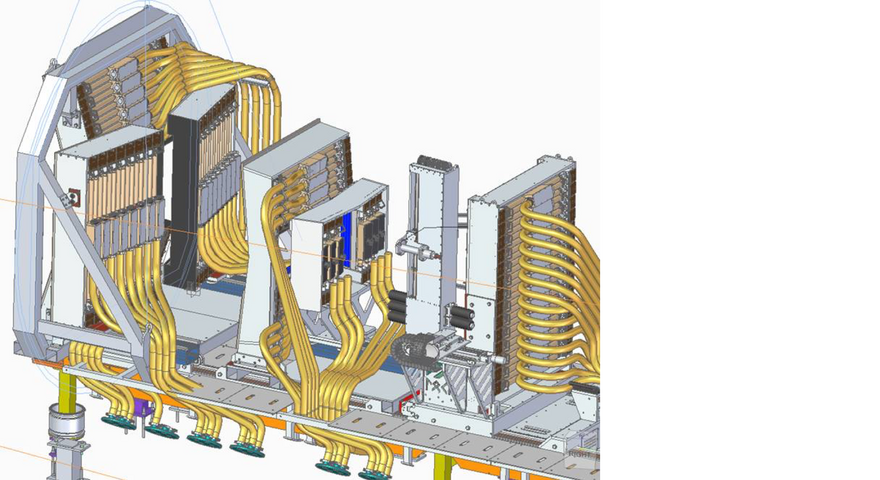
LoKI Instrument Detector

Boron Coated Straw Tubes are advanced neutron detectors that have been developed by Proportional Technologies Incorporated in the USA for applications in scientific research, particularly in Small-Angle Neutron Scattering (SANS) instruments. These detectors offer improved performance compared to traditional 3He tubes in terms of speed and position resolution.
Each Boron Coated Straw Tube detector comprises seven resistive wire tubes, each with a diameter of 7.5 mm, which are coated on the inside with a thin layer of 10B4C, a boron-based compound. These seven tubes are arranged in a hexagonal pattern inside a 25.4 mm diameter aluminum tube. The volume within this tube is filled with an argon-based gas mixture.
The utilization of Boron Coated Straw Tubes in SANS instruments offers several advantages. Firstly, these detectors demonstrate enhanced speed, enabling faster data acquisition and analysis. Additionally, they provide superior position resolution, allowing for precise determination of the scattering angles of neutrons.
However, it is important to note that Boron Coated Straw Tubes exhibit a lower neutron detection efficiency compared to traditional 3He tubes. To compensate for this, a total of five layers of these detectors are required to meet the efficiency requirements of instruments like LoKI.
In conclusion, Boron Coated Straw Tube technology represents a significant advancement in neutron detection for SANS instruments. With their improved speed and position resolution, these detectors offer researchers enhanced capabilities for studying the nanoscale structure and behavior of materials. By combining innovation with efficient neutron detection, Boron Coated Straw Tubes contribute to the advancement of scientific knowledge in various fields of research.
Front End Electronics
In the Loki SANS instrument, the implementation of multiplexing techniques significantly reduces the number of required readout channels for the Boron Coated Straw Tubes (BCSs). This method involves connecting a resistive chain between the BCSs at both ends, as illustrated in the diagram. The resistance between each BCS is set to 22 Ω, which is intentionally chosen to be much smaller than the resistance of the BCS wires (approximately 4 kΩ). This minimizes the impact of the chain resistance on the position calculation along the length of the BCSs. The resistive chain is housed on a compact printed circuit board (PCB) that fits within the aluminum body of the tube.
The seven BCSs are readout by four preamplifiers connected at specific corners (A, B, C, and D) of the circuitry. The position calculation of neutron absorption within the BCSs utilizes the center of gravity along the x-axis (as per equation 1). Additionally, the center of gravity along the y-axis is employed to determine the interaction point along the length of the BCSs (according to equation 2).
The multiplexing technique offers notable performance benefits. It allows each 1" tube to operate at frequencies up to 400 kHz, with a 10% count rate loss and a position resolution of 10 mm. This translates to a potential total count rate of 2 MHz across an area of 2.54x100 cm2, assuming equal neutron detection in each detector layer.
By employing this multiplexing method, the number of preamplifiers, cables, and analog-to-digital converter (ADC) channels required can be reduced by a factor of 3.5. For instance, a 1 m2 detector, such as the rear detector of Loki, would only need 800 preamplifiers and ADC channels instead of the original 2800. In terms of hardware, 17 ADC boards, similar to those used in WISH and SANS2D instruments, will be necessary but will require an upgrade to operate at a higher sample rate of 125 MHz (ADC sample rate).
Overall, the implementation of multiplexing techniques in the Loki SANS instrument significantly reduces the hardware complexity while maintaining performance standards, allowing for more efficient and cost-effective data acquisition and analysis.

Detector Layout
In the Loki SANS instrument, the neutron detection system is divided into three distinct detector banks: the front bank, middle bank, and rear detector. These components are strategically positioned to cover different ranges of scattering angles, allowing for comprehensive data collection and analysis.
The front bank is designed to capture scattering angles ranging from 20° to 41°. It is composed of two horizontal arrays and two vertical arrays, providing enhanced coverage and sensitivity. This configuration ensures that neutron scattering events within this angular range are effectively captured and measured.
The middle bank is responsible for detecting scattering angles from 4.5° to 20°. Similar to the front bank, it consists of two horizontal arrays and two vertical arrays. By placing the middle bank at an intermediate position, it enables precise measurements in this specific scattering angle range, contributing to a more comprehensive understanding of the sample’s structure and properties.
The rear detector, unlike the front and middle banks, is designed to be movable. It can be positioned at either 5 meters or 10 meters from the sample position. This flexibility allows the rear detector to cover scattering angles from 0° to 6° effectively. By adjusting the distance between the rear detector and the sample, a wider range of low-angle scattering events can be captured, contributing valuable data for the analysis of large-scale structures and molecular interactions.
The strategic arrangement of these detector banks in the Loki SANS instrument ensures comprehensive coverage of scattering angles across a wide range. This enables researchers to obtain detailed information about the sample’s structural properties at different length scales, enhancing our understanding of the materials under investigation.

Detector Readout
In the readout system of the Loki SANS instrument, approximately 50 units of the R5560 digitizer module from CAEN are employed (https://www.caen.it/products/r5560/). This choice offers several advantages for the instrument’s operation.
The R5560 digitizer module is known for its high performance and reliability, making it suitable for demanding scientific applications. It provides fast and accurate data acquisition capabilities, allowing for efficient signal processing and analysis. Its wide dynamic range and high sampling rates ensure the capture of detailed information from the neutron detection system.
One notable advantage of using the R5560 is its compatibility with SciCompiler, a versatile firmware development tool. SciCompiler enables flexible customization of the digitizer’s firmware to meet specific requirements and optimize performance. This adaptability allows researchers to tailor the digitizer’s functionality according to the specific needs of the Loki SANS instrument.
The use of a differential signal over an RJ45 cable, instead of single-ended coaxial cables, provides economic and signal quality benefits. Differential signaling minimizes electromagnetic interference and reduces noise, resulting in improved signal integrity. This approach ensures better data accuracy and a higher signal-to-noise ratio, enhancing the quality of acquired neutron scattering data. Moreover, the utilization of RJ45 cables offers cost advantages compared to specialized coaxial cables, contributing to overall cost-effectiveness of the readout system.
At STFC (Science and Technology Facilities Council), the designers of the Loki SANS instrument leveraged the SciCompiler firmware development tool to develop the firmware for the instrument’s readout system. Utilizing SciCompiler significantly expedited the firmware development process, allowing the designers to complete the task in just a few weeks.
SciCompiler provided a versatile and efficient platform for firmware customization, enabling the designers to tailor the readout system’s functionality to meet the specific requirements of the Loki SANS instrument. The tool’s user-friendly interface and comprehensive features facilitated the implementation of various desired functionalities and optimizations.
By utilizing SciCompiler, the designers were able to streamline the firmware development process and efficiently integrate the required functionalities into the readout system. This approach reduced the overall development time, enabling a swift turnaround from design to implementation. The ability to rapidly iterate and test firmware modifications contributed to the efficiency and effectiveness of the development process.

LoKI SciCompiler Firmware
The firmware developed using SciCompiler for the Loki SANS instrument’s readout system is divided into the following components, each serving a specific function:
-
Signal Acquisition: This part of the firmware is responsible for capturing the incoming signal from the neutron detection system. It ensures accurate and precise data acquisition by sampling the signal at high speeds and converting it into digital form for further processing.
-
Semi-Gaussian Filtering for Noise Removal: To enhance the signal quality, a semi-Gaussian filtering technique is implemented. This filtering process helps remove noise and unwanted artifacts from the acquired signal, resulting in improved data integrity and reliability.
-
Peak Detector: The peak detector component identifies the peak positions within the acquired signal. It analyzes the signal amplitude to determine the peak positions accurately. This functionality is crucial for accurately detecting neutron events and extracting relevant information from the data.
-
Center of Mass Calculation: The center of mass calculation module determines the center of mass along the x and y axes for each detected neutron event. This calculation is essential for accurately determining the position of the neutron interaction within the neutron detection system.
-
Data Transfer to the Readout System: Once the relevant information is extracted and processed, the firmware facilitates the efficient transfer of data to the readout system. This ensures that the acquired data is seamlessly transmitted for further analysis and storage.
-
Integrated Oscilloscope Monitoring: The firmware includes an integrated oscilloscope feature, allowing real-time monitoring of the acquired signal within the readout system itself. This enables researchers to visualize the signal characteristics and verify its quality and integrity without the need for external monitoring tools.
Integration in ESS readout system
Nuclear Instruments, in collaboration with ESS (European Spallation Source), has integrated the R5560 device and developed a variant of it using SciCompiler. This variant is specifically designed to enable optical communication within the ESS readout system.
The ESS detector system consists of both back-end and front-end nodes, each playing a crucial role in the overall functionality of the system.
-
Back-End Node: The back-end node is responsible for the centralized processing and distribution of data acquired from the front-end nodes. It performs various tasks, including data readout, processing, and analysis. The back-end node aggregates the digitized signals from the front-end nodes, applies advanced algorithms for event reconstruction and data reduction, and prepares the data for further analysis. This node also handles the synchronization of data acquisition across different detectors and manages the overall timing system. The back-end node is typically a high-performance computing system with multiple processing units and a large storage capacity to handle the substantial amount of data generated by the detector system.
-
Front-End Node: The front-end nodes are situated near the detectors and perform the initial signal processing and digitization. They are responsible for capturing the raw analog signals from the detectors and converting them into digital form for further processing and analysis. The front-end nodes are designed to be modular and scalable, allowing for flexibility in integrating different detector technologies. They include components such as ASIC based readout system, digitizers, counters. The front-end nodes are also responsible for maintaining the synchronization with the central timing system to ensure accurate time-stamping of the acquired data.

The front-end nodes are closely connected to the back-end node through a high-speed data communication infrastructure, which enables the efficient transfer of digitized data for further analysis and storage. This communication link ensures that the data collected by the front-end nodes is seamlessly transmitted to the back-end node for processing and analysis.

The integration of the R5560 as a front-end component within the ESS detector system involves incorporating it into the front-end node architecture. The R5560, provided by Nuclear Instruments, acts as a digitizer module and performs signal processing and data acquisition tasks at the front-end level. By customizing the firmware of the R5560 using the SciCompiler tool, it is tailored to meet the specific requirements of the ESS system, ensuring efficient and accurate data acquisition.
By utilizing SciCompiler, Nuclear Instruments and ESS were able to customize the firmware of the R5560 device to support optical links for seamless communication within the ESS readout system. This integration allows for efficient and reliable transmission of data, clock, and timestamp information.
The optical link is utilized to synchronize the entire data acquisition process with other instruments present in the ESS facility. This synchronization ensures that all data acquisition within ESS is precisely coordinated, allowing for accurate time-stamping and synchronization across multiple instruments.
The utilization of optical links for data, clock, and timestamp transmission offers several advantages. Firstly, it enables high-speed and low-latency communication, facilitating real-time data processing and analysis. Secondly, optical links provide robust noise immunity, ensuring accurate and reliable transmission of critical timing and data information. Lastly, the synchronization of acquisition with other instruments ensures coherent data collection, enhancing the accuracy and integrity of scientific measurements performed at ESS.
Through the integration of the R5560 device variant and the use of optical links for data and timing transmission, Nuclear Instruments and ESS have achieved synchronized and coordinated data acquisition within the ESS readout system. This advancement enhances the overall performance and reliability of neutron detection systems, enabling precise and accurate scientific research at the ESS facility.
Preliminary Result
Loki, the neutron detector system, is currently in the assembly phase and has not yet been installed at ESS (European Spallation Source). However, a subset of the Loki detector has been tested on the SANS (Small Angle Neutron Scattering) Larmor instrument at ISIS (a world-leading pulsed neutron and muon source located in the UK). This testing allowed for preliminary evaluation and validation of the detector’s performance.
During the testing phase, a sample was examined using the Loki detector, and the obtained results showcased the capabilities of the system. While I am unable to directly process or display images, the data obtained from this preliminary test demonstrated the detector’s ability to capture and analyze neutron scattering at small angles. The results obtained from the sample provided valuable insights into the instrument’s sensitivity, resolution, and overall performance.

These preliminary results highlight the promising potential of the Loki neutron detector system in advancing neutron scattering research. As Loki continues its development and approaches its installation at ESS, these preliminary findings serve as a valuable indication of the instrument’s capabilities and contribute to its optimization for future scientific investigations at ESS.