Case-Study Case-Study, RF, DSP, Signal Processing
A lock-in amplifier is the standard answer to one specific problem: you have a signal you can modulate, and it is far smaller than the noise sitting on top of it. Chopped optical transmission, photothermal and photoacoustic spectroscopy, impedance and bioimpedance measurement, magneto-optical rotation, capacitive and inductive position sensing, resonant gas sensors. In all of them the experiment can be driven at a frequency of your choosing, and the answer is the amplitude and phase of the response at exactly that frequency.
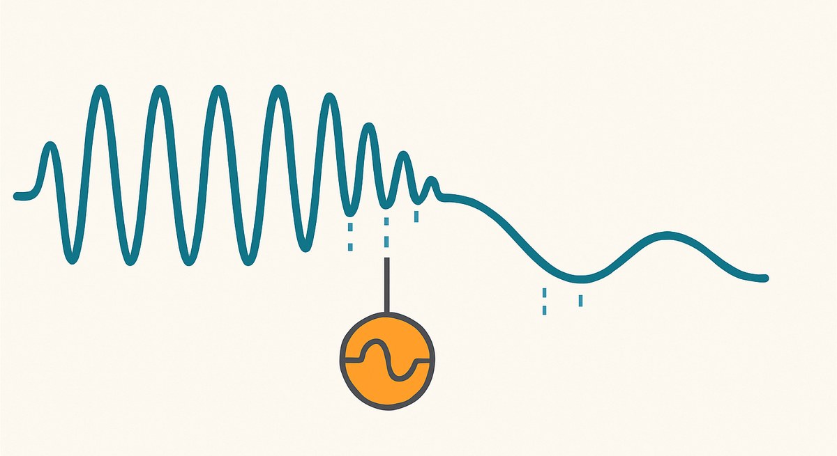
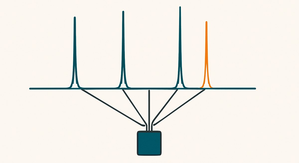
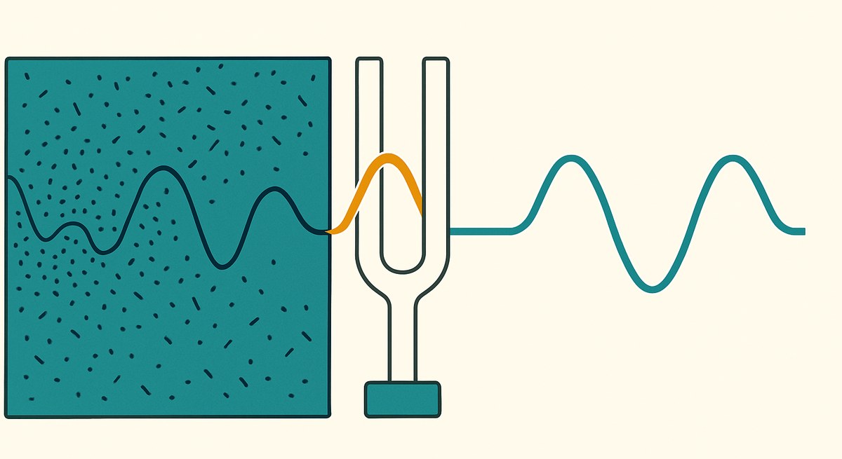
The technique works because noise is spread over the whole spectrum and the signal is not. If you can restrict your measurement to a band a fraction of a hertz wide, centred exactly on the modulation, you throw away essentially all of the noise and keep essentially all of the signal.

Three blocks
The whole instrument is three blocks and a reference.
NCO generates the reference at the modulation frequency, as a complex I/Q pair. The same NCO can drive the physical modulator, which removes the entire problem of phase-locking to an external reference: the drive and the demodulation reference are the same numbers.
Mixer multiplies the incoming detector stream by that reference. This is the step that does the work. Multiplying by a sinusoid at f_ref translates everything at f_ref down to DC and everything else to somewhere that is not DC.
Moving Average, or a CIC for long integrations, is the low-pass that follows. This block is the actual instrument: it is what decides the noise bandwidth. Everything before it merely arranged for the signal to be at DC and the noise not to be.
CORDIC converts the surviving complex value to magnitude and phase, which is what the experiment wanted all along.
The only parameter that matters
The integration length is the whole design. It sets the equivalent noise bandwidth, and therefore both how much noise survives and how fast the instrument can respond to a real change. There is no way to improve one without paying in the other.
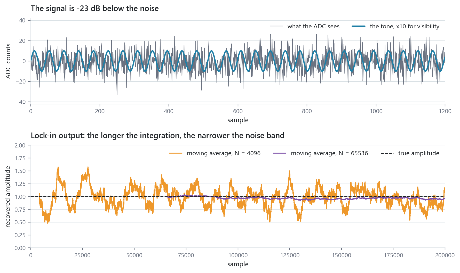
The upper panel is the raw input, with the tone drawn separately at ten times its real size just so it is visible on the page at all: at the amplitudes shown, the signal is 23 dB below the noise and completely invisible in the trace. The lower panel is the output of the chain for two integration lengths.
The behaviour is exactly the square-root law you would expect. Going from 4096 to 65536 samples, a factor of 16 in integration time, cuts the scatter on the recovered amplitude by a factor of four. The shorter integration responds quickly and wobbles; the longer one is quiet and slow. Which of the two is right is a property of your experiment, not of the amplifier, and the point of implementing it this way is that changing your mind costs a register write.
The Goertzel alternative
There is a second way to get the same answer, and it is worth knowing which one you want.
The Goertzel Sliding block maintains a single DFT bin over a sliding window of N samples and outputs its power on every input sample. Mathematically this is a very close relative of what the lock-in chain does, but the arithmetic is different: a second-order resonator instead of a multiply-and-integrate, and the window is rectangular and exactly N long rather than an exponential or boxcar average you chose.
The practical differences are these. The Goertzel gives you power, not amplitude and phase, unless you take the complex output. Its noise bandwidth is fixed by N and by nothing else. The mixer-and-average chain gives you phase for free, which matters whenever the phase is the measurement, as it is in impedance spectroscopy, and it lets you pick the low-pass independently of any block length. If you want phase, build the chain. If you only want power at one frequency and you want it cheap, take the Goertzel.
What it replaces
A commercial lock-in amplifier is an instrument on a bench with a front panel. This is a handful of blocks on a schematic sheet, sitting directly behind the ADC that is already digitising the detector, with the modulation drive generated by the same design. There is no analog reference path to phase-match, no cable between the modulator and the demodulator, and the reference is exact rather than merely accurate.
It also scales in a way a bench instrument does not. If the experiment has sixteen detector channels, all the blocks in this chain have time-multiplexed twins, and sixteen lock-ins share one set of hardware.
This is a reference design. The chain and the block behaviour are as documented; the figures are computed from the models described, not measured on an instrument.