Case-Study Case-Study, Signal Generation, Timing, Detector
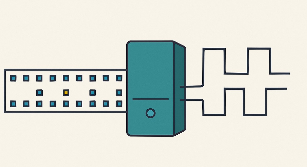
Most detector systems need a set of digital signals to happen in a precise order, over and over. Configure an ASIC by clocking a shift register with the right chip-select framing. Fire a calibration LED, wait a fixed delay, open an acquisition gate. Step a laser through a set of positions with a settling time between each. Run a charge-injection sequence across sixteen channels in turn.
None of this is difficult logic. It is, however, exactly the kind of logic that gets written as a state machine, then modified, then modified again, until the state machine encodes a timing diagram that exists only in somebody’s head and cannot be changed without re-synthesising.

The sequence as data
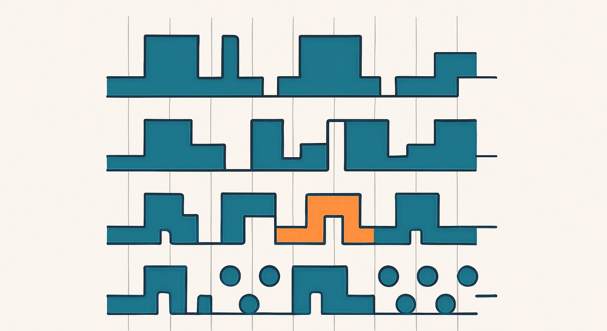
The Sequencer Generator takes the opposite approach: the sequence is a table in ROM, one vector per step, and the block plays it back. Define any number of digital signals, draw what each one does, and the block emits them.
The consequence is that the timing diagram is the design. There is no translation step between the diagram in the specification and the logic in the device, and therefore no opportunity for the two to drift apart. When the ASIC vendor changes the setup time on the chip select, you move an edge.
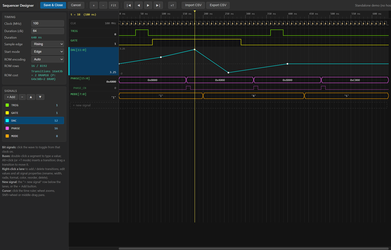
Everything about the sequence is visible at once, and three details in that screenshot are worth pointing at.
The ROM cost line in the timing panel is a live estimate, and it shows both encodings side by side — 16 transitions at 43 bits against a 64×38 dense table — so the memory consequence of an edit is visible while you make it, not after synthesis.
DAC[11:0] is drawn as an interpolated analog trace rather than twelve separate bits, because that is what it is. MODE[7:0] is formatted as ASCII. PHASE_CN is the change-notification bit that pulses when the PHASE bus takes a new value.
A few things make this practical rather than merely tidy:
Pattern generators. Right-click a signal and choose from eighteen generators — clocks, counters, walking ones, pseudo-random sequences and so on — instead of drawing three hundred edges by hand.
Analog display mode. Any signal can be displayed as a bus, an analog step or an interpolated trace, gtkwave style, which is what you want when a group of bits is really a DAC code being ramped.
Dual ROM encoding. The VHDL is generated either as a transition list or as a dense table, whichever is smaller for the pattern you actually drew. A sequence that is mostly idle with occasional activity costs almost nothing; a dense one is stored densely.
Change-notification output. An optional extra bit per vector that pulses when the vector changes, which saves building an edge detector downstream for the common case of “do something when this step begins”.
Where the determinism matters
For ASIC configuration the requirement is simply correctness: setup and hold on the chip select relative to the clock, a defined number of clocks, no glitches. A pattern player satisfies this by construction, because every edge is placed on a clock boundary by the table.
For calibration the requirement is different and stronger. If you are firing an LED and measuring the response, the jitter between the fire and the gate is part of your measurement. A sequence played from ROM at a fixed step rate has jitter of exactly zero relative to the design clock: not “low”, zero, because the same counter produces both edges. Nothing running on a host, and no software timer, can offer that.
This is the same reason the Periodic Pulse block exists for the simpler case where all you need is a repeating pulse with a programmable period and width.
Combining it with the rest
A sequencer becomes considerably more interesting when its output is not the end of the story.
Driving the calibration LED from the sequencer and the acquisition gate from the same table means the two are locked. Feeding the resulting pulses into the Waveform Averager, triggered from the same sequence, means the averaging is coherent by construction and a calibration template accumulates without any trigger logic at all.
For a channel-by-channel charge injection, the sequencer supplies the channel index and the injection strobe, and a Histogram Analyzer per channel, or one time-multiplexed instance, collects the response. The whole calibration run is then a sequence table and a readout, with no host involvement in the timing.
The practical argument
The reason to prefer this over a hand-written state machine is not that the state machine is hard. It is that the sequence is the part of the design most likely to change, most likely to change under time pressure, and least likely to be re-verified after it changes.
Making it data rather than logic means a change is a table edit, the diff is readable, and the thing that gets reviewed is the timing diagram rather than a case statement that implements one.
This is a reference design. The block behaviour and the encoding options are as documented; the timing figure is illustrative of the block’s output form.