Case-Study Case-Study, Signal Generation, Testing, Design Flow
Firmware development almost never starts with all the hardware on the desk. The ADC daughterboard is six weeks out. The ASIC is in fabrication. The sensor exists but is installed at a facility three hundred kilometres away and gets an access slot next month. The bus you have to speak to is on a system that works, and nobody will let you experiment on it.
In every one of those cases the digital interface is known — there is a datasheet, or a captured trace — and what is missing is something to talk to.

The block
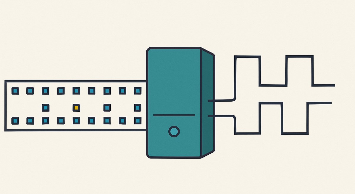
The Sequencer Generator is a pattern player: the sequence is a table in ROM, one vector per step, and the block emits it. Its companion, the Pattern Generator, does the same from a data file loaded through the Rom Content property, with configurable bit width, memory depth and several data formats.
Neither block knows or cares what the pattern means. That is precisely what makes them useful here: a serial protocol, a training sequence, a sensor’s startup handshake and a captured bus trace are all, from the block’s point of view, the same thing — a list of vectors to put on some pins.

What this makes possible
Develop the receiver before the transmitter exists. If the ADC’s LVDS training pattern is in the datasheet, it can be in a ROM this afternoon, and the deserialiser and word-alignment logic can be written, simulated and debugged against it. When the real board arrives, the interface has already been exercised.
Reproduce a failure. A bus trace captured from a system that misbehaved once is a table of vectors. Loaded into the sequencer, that exact sequence replays on every run, as many times as needed. This is the difference between a bug you can work on and a bug you wait for.
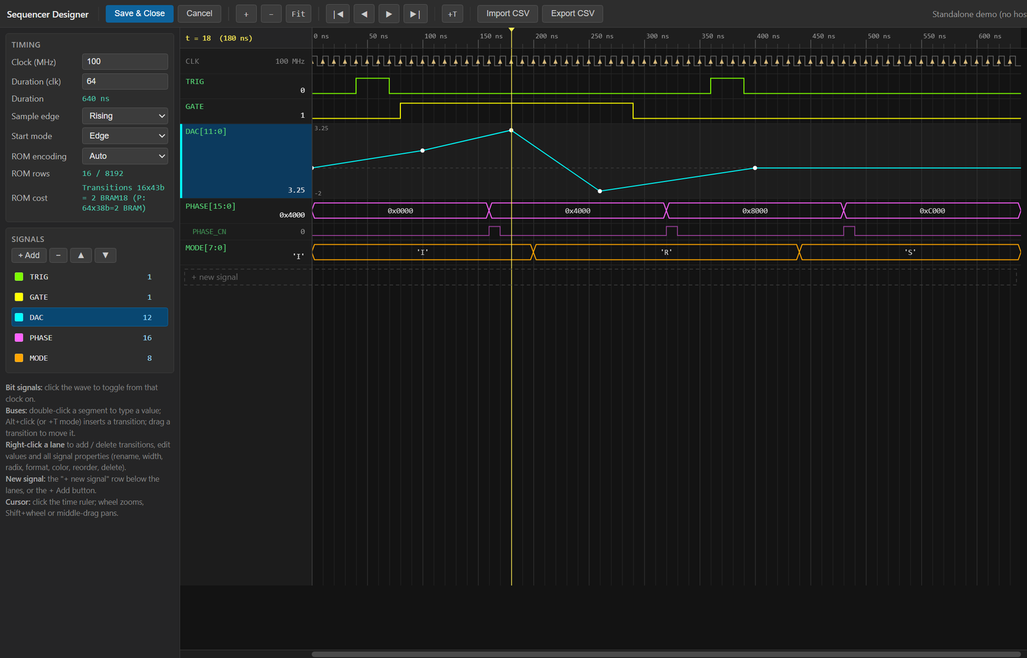
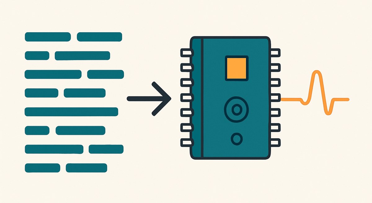
The Import CSV button in the designer is what makes that practical: a trace exported from a logic analyser goes straight in, and once it is there it can be edited — truncate the frame, corrupt one field, delete an acknowledgement — to produce the variants the real system never obliged you with.
Test the paths nobody can reach. A real device produces its error conditions when it feels like it. A pattern player produces them on request: a truncated frame, a bad CRC, a missing acknowledgement, a device that stops responding halfway through a transaction. These are the paths where firmware fails in the field and where it is least often tested, precisely because provoking them on real hardware is difficult or impossible.
Regression-test an interface. Because the sequence is data and the playback is deterministic to the clock, an interface test is exactly repeatable. Combined with the Docker image for CI, the handshake can be re-verified on every commit.
Building the pattern
Drawing a long sequence edge by edge would defeat the purpose, and the block does not ask you to. Right-clicking a signal offers eighteen pattern generators — clocks, counters, walking ones, pseudo-random sequences — so the repetitive parts are generated and only the interesting parts are drawn.
Signals can be displayed as a bus, an analog step or an interpolated trace in the gtkwave style, which matters when a group of bits is really a word: a payload counter or a DAC code is far easier to check as a number than as eight separate traces.
The generated VHDL uses one of two ROM encodings, a transition list or a dense table, whichever is smaller for the pattern actually drawn. A protocol frame with long idle stretches costs almost nothing; a densely toggling one is stored densely. And an optional change-notification bit per vector pulses when the vector changes, which saves building an edge detector downstream.
Where it sits next to the other generators
This is one of three ways to make a design believe hardware is present, and they cover different layers.
The detector emulator works at the level of events and energies: Poisson arrivals carrying amplitudes drawn from a real isotope spectrum. It tests the physics chain.
The noise sources work at the level of the analog sample: a specified spectrum and distribution on the ADC bus. They test the signal-processing chain.
Pattern playback works at the level of the digital interface: bits and edges on wires with specified timing. It tests the part of the design that talks to the outside world, which is the part that cannot be tested by any amount of good behaviour further downstream.
The same block also has a role once the hardware exists, driving your own devices rather than impersonating other people’s — ASIC configuration, calibration timing, deterministic sequences — and that is the subject of a separate case study.
The boundary
A pattern player reproduces what a device sends. It does not react to what your design sends back, because a table has no state.
For a stimulus that must respond — a device that acknowledges, that changes behaviour depending on a command, that arbitrates — you need a model with logic in it, and the honest place for that is a small state machine, or an imported VHDL model through the Custom HDL block.
In practice a surprising fraction of real interfaces are open loop from the device’s side, or close enough that a fixed replay covers the case that matters: an ADC that streams, a sensor that pushes samples, a timing system that broadcasts. For those, a table is the whole model.
This is a reference design. The block behaviour and the encoding options are as documented; the timing figure is illustrative of the block’s output form.