Case-Study Case-Study, Multi Channels, Design Flow, DSP
Every block in the Sci-Compiler library now exists in two versions, and the second one is marked TM. Understanding what that means takes about ten minutes and saves a great deal of confusion, because TM is one mechanism that solves two quite different problems, and the mechanism cannot tell you which of the two you are using it for.
The problem it was built for
The VX2730 and DT2730 digitisers sample at 500 MS/s. The FPGA inside them runs at 125 MHz, which is one clock cycle every 8 ns.
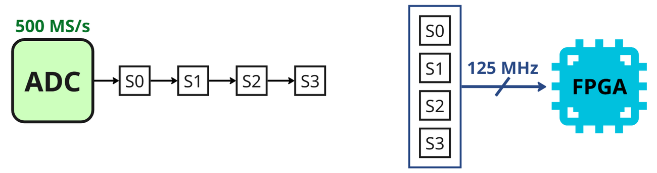
Four ADC samples arrive during every single FPGA clock cycle. A standard processing block consumes one sample per cycle. Connect the analog input straight to one and three samples out of four have nowhere to go: you lose data, or you misalign the stream, and neither failure is loud.
This is not a shortcoming of the digitiser or of the tool. It is what happens whenever the front end is faster than the fabric, and it becomes more common with every generation of converter.
What a TM signal actually is
A TM signal is TM_FACTOR lanes packed into one wide word, carried on one bus, one word per clock.
On the 2730 the analog input is a [4x16] bus: 64 bits carrying four 16-bit samples. Lane 0 sits in the low bits, and lane 0 is the oldest sample of that clock. That packing convention is the same for every TM block in the toolchain, which is what lets them be wired together freely.
Approach one: TM blocks
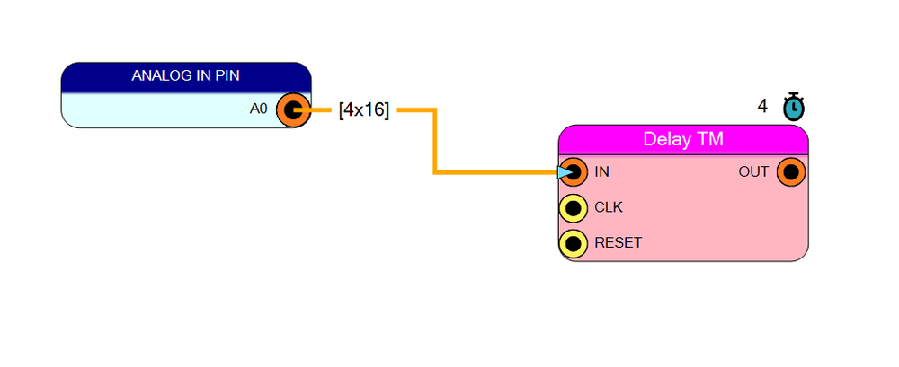
A TM block accepts the packed word and processes every lane inside the same clock cycle. Internally it replicates the per-lane logic; externally it is one block on the sheet with one wire into it.
This is the recommended route, and the reason is not only convenience: the timing alignment between lanes is handled by the block rather than by you, which removes an entire category of bug that is very hard to see in a waveform.
Approach two: split, process, repack
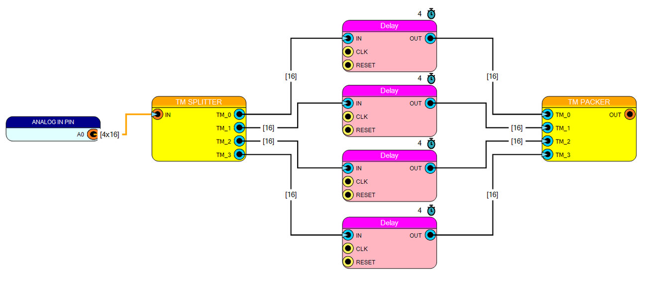
The alternative is to break the bus apart with a TM Splitter, run four ordinary blocks, and put the lanes back together with a TM Packer.
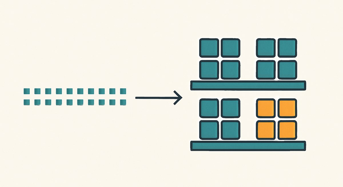
That picture is worth looking at for a moment, because it is the resource argument made visible: the same job needs four copies of the Delay block instead of one. On the other hand it is genuinely the right answer in two cases — when the block you need does not have a TM twin yet, and when you actually want to treat the lanes differently, which a TM block will not do for you.
The full set of conversions is small and worth knowing:
TM Packer takes N separate scalar signals and concatenates them into a TM bus. TM Splitter does the inverse. TM Phase Extractor pulls one chosen lane out as a scalar. TM Signal Replicator broadcasts one scalar to every lane, which is how a threshold or a constant enters a TM datapath. STD / TM Converter goes in all four directions and enforces the one rule that matters: input width times input TM factor must equal output width times output TM factor, because nothing is created or destroyed by repacking.
The second life of TM, and the thing to keep straight
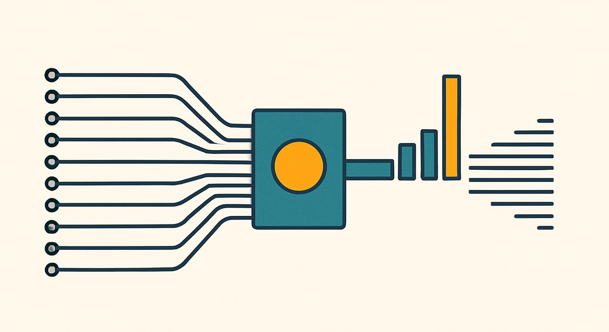
TM Packer is where the story turns. It takes independent signals and packs them, which means the lanes of a TM bus need not be consecutive samples of one channel at all — they can be sixteen different detector channels.
Do that, and one TM block serves sixteen channels. This is the basis of the per-channel diagnostics design and one half of the multichannel decision.

Here is the point of this whole case study. The block cannot tell the two situations apart. Its arithmetic is per lane in both cases. What differs is what a lane means, and that is a fact about your design that lives nowhere in the netlist.
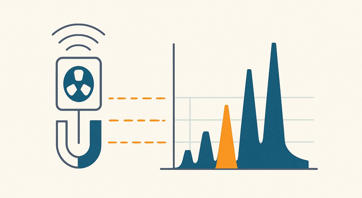
The consequence is worth spelling out, because it is where people go wrong. Put a fast single-channel 2730 stream into Block Mean TM and you do not get the mean of the signal. You get four means: one over samples 0, 4, 8, …, one over samples 1, 5, 9, … and so on. That is a polyphase decomposition, and it is a perfectly sensible thing to compute — it is how you would look for an interleaving mismatch between the ADC’s own sub-converters — but it is not what someone who wanted “the average of this signal” was asking for.
When the lanes are channels, the same block gives you sixteen channel means, which is exactly right.
Same block, same numbers, entirely different meaning. Nothing in the tool will warn you, because nothing in the tool knows.
What stays scalar
A TM block does not simply become N copies of itself. Three things are shared, deliberately.
The frame. One EXP, one IN_DV, one OUT_DV per block. Every lane starts and ends together, so BUSY, INTEGRATING and SAMPLE_COUNT stay scalar — the per-lane sample counts are identical by construction.
Broadcast parameters. A threshold, a hysteresis, a lag, a block size: these stay one scalar pin, latched per block and applied to every lane.
The expensive arithmetic. The dividers, the square roots and the wide once-per-block products are one set, serving the lanes one after another. This is where the area saving comes from, and it is why TM pays off most on blocks whose tail is expensive.
What must not be shared is per-lane state, and the library is careful about this: a Schmitt-trigger state, a held previous sample, a lag delay line all stay strictly per lane, because sharing any of them bleeds one lane’s history into another.
The price is in the tail latency. For the serially-tailed statistics blocks it is L_tm = TM × (L_scalar − 1) + 1, with a handful of documented exceptions. For a block computed once over thousands of samples that is invisible; for a fast feedback path it may not be.
Practical notes
The TM factor range depends on the block: 2 to 16 for the statistics family, 2 to 32 for the bitwise and conversion blocks.
TM blocks are orange in the toolbox, so a mixed design shows at a glance where the boundary between the packed and the scalar domain falls — and that boundary is where the Splitter, Packer and Replicator belong.
TM ports work inside sub-designs, so a TM datapath can be a replicated channel block.
If you want to learn this without owning a fast digitiser, the SciDK TM board is a virtual target that exposes TM blocks in a SciDK project, which is the cheapest way to make the packing conventions concrete.
When not to use it
Two cases.
If the design is genuinely one channel at a rate the fabric handles comfortably, TM adds packing complexity and buys nothing.
And if you are using TM to serve many channels, remember that one TM block serves one lane per clock: the channel sample rate multiplied by the lane count cannot exceed the system clock. Sixteen lanes at 250 MHz leave about 15 MS/s per channel. That ceiling, not the area, is usually what decides the design.
This is a reference article. The clock relationship, the packing convention, the two approaches and the conversion blocks are as documented in the user guide and the block reference; the figures in the first half are the guide’s own.